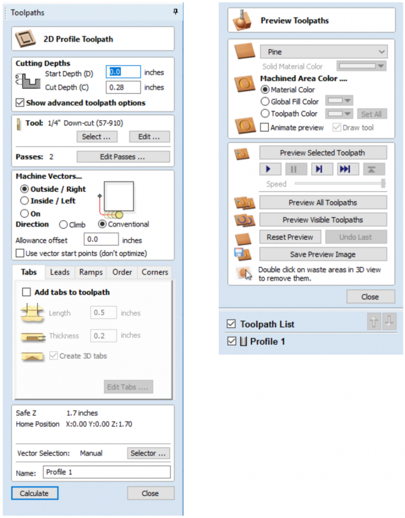
- Cutting Depths needs two parameters; start depth and cut depth. Start Depth will typically be 0.0” while Cut Depth is how far the end mill goes through your material. (Make sure to add some extra length to the cut depth that so that you’re sure the bit cuts all the way through your material: 0.02” is a good number)
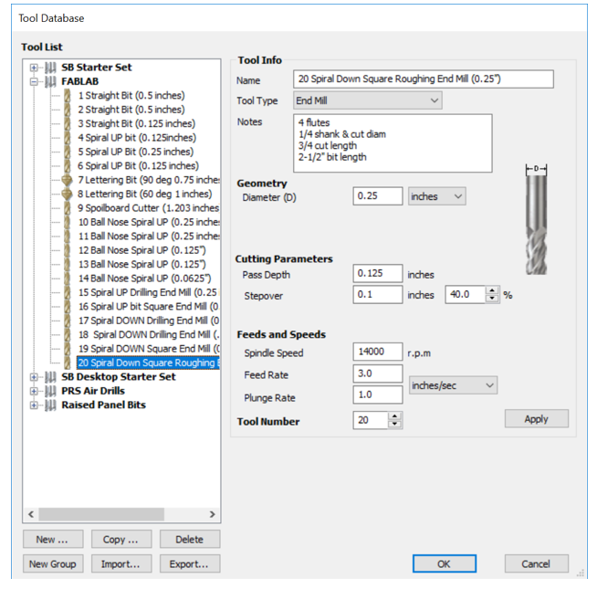
- Tool gives you the option to select which end mill you want to use. The selection of the end mill is very important. This depends on the type of cut you will be doing and the material you want to cut. The DMA Fab Lab provides about 20 bit options for you to use; however, your cut may require you to buy your own bit. To determine which bit to use, check out the table sheets provided by the lab.
- Select is for selecting the bit you want to use. See more info in the picture.
- Edit is to edit the bit that you have selected. This should be used only if you are not using one of the lab drill bits, and brought in your own bit.
- Passes is how many rounds the drill will make to cut through your material.
- Edit Passes button will open a new dialog that enables the specific number and height of passes to be set directly.
- Machine Vectors There are 3 options to choose from to determine how the tool is positioned relative to the selected vector(s):
- Machine Vectors There are 3 options to choose from to determine how the tool is positioned relative to the selected vector(s):
Outside → Calculates a profile toolpath around the Outside of the selected vectors, with options for the cut direction to be either Climb (CW) cutting direction or Conventional (CCW) cutting direction

Inside → Calculates a profile toolpath around the Inside of the selected vectors, with options for the cut direction to be either Climb (CCW) cutting direction or Conventional (CW) cutting direction

On → Calculates a profile toolpath on the selected vectors, with options for the cut direction to be either Climb (CW) cutting direction or Conventional (CCW) cutting direction
- Conventional(CCW) is to move the machine arm right to make a cut (not the bit rotation.) We recommend you check this option.*
*However, this is also depends on what shape you cut and the Outside or Inside options you have selected.- Allowance Offset An Allowance can be specified to either Overcut (negative number will cut smaller) or Undercut (positive numbers will cut larger) the selected shape. If the Allowance = 0 then the toolpaths will machine to the exact size.
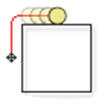
- Use vector start points (don’t optimize)
- Use Start Point can be selected to force the toolpath to plunge and start cutting at the first point on the shape. This is very useful if you need to ensure the cutter doesn’t plunge onto a critical part of the job. For example, setting the Start Point to be on a corner will often be the best position to plunge and cut from as this will not leave a witness / dwell mark on the machined surface.
- The Start Points are displayed as Green boxes on all vectors when this option is selected. Start Point on a vector can be moved using the Node Editing Tools. Select Node Editing cursor or press N. Place the cursor over the node to be used as the Start Point. Click Right mouse button and select Make Start Point (or press P) Remember, you can also insert a new point anywhere on a vector using the Right mouse menu or pressing the letter P – this will insert a new point and make it the start point.
- Note: Selecting Use Start Point may result in less efficient toolpaths (increased cutting times) because it may take the machine longer to move between each shape being cut. If this option is not selected the software will try to calculate the shortest toolpath, minimizing the distance between link up moves. But the downside is that the cutter may plunge/mark important surfaces on the machined edge.
- Tabs (Bridges)
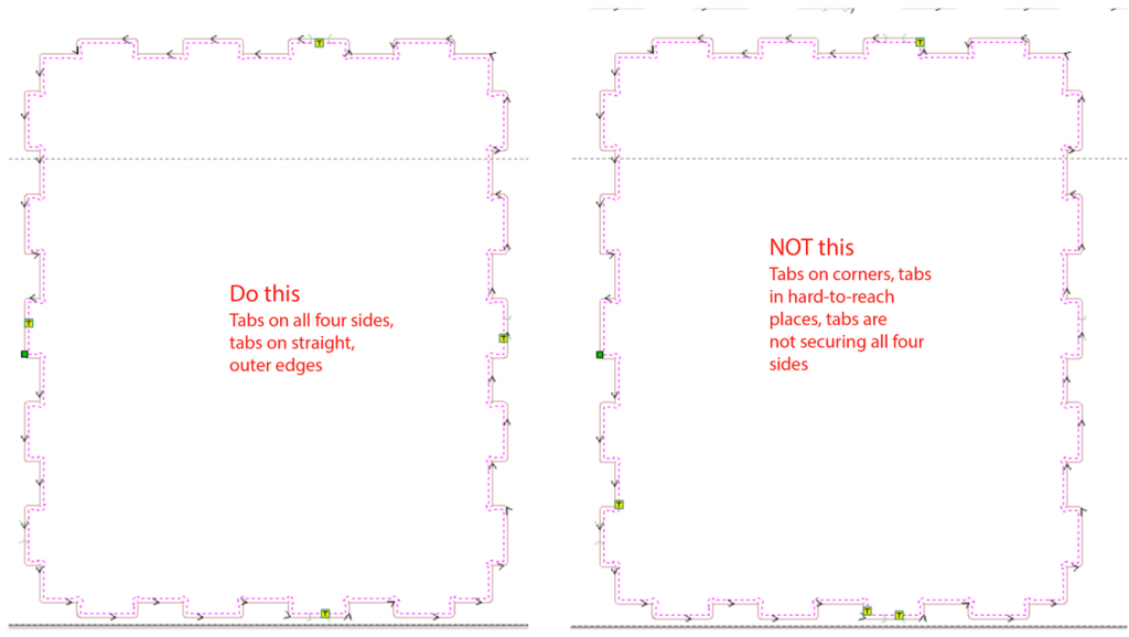
- You must add tabs to both open and closed vector shapes to hold parts in place when cutting them out of material.
- Add tabs to toolpath
- Checking ✓ the Add tabs option will activate tab creation for this toolpath.
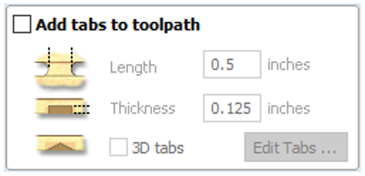
- Edit Tabs
- Clicking on the Edit Tabs… button automatically opens the 2D window and the Toolpath Tabs form is displayed:
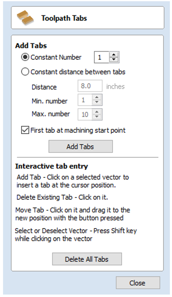
- Add Tabs
- Constant Number… Calculates the length of each selected vector and places ‘X’ number of equally spaced Tabs around the shape.
- Constant Distance between tabs… This option places a tab at the specified distance around the selected shape.
- If placing tabs at the Distance around the shape results in fewer than the Min. number, the minimum number of tabs are automatically equally placed on the shape.
- If the number of tabs calculated using the Distance around the shape is greater than the specified Max. number, the maximum number are placed at equal distance around the shape.
- First tab at machining start point… If checked(✓) a tab will be placed at the start point (Green node) of a vector when the option First Tab at Machining Start Point is selected.
- Dynamically positioning tabs in the 2D View
- The quickest method for adding Tabs to multiple shapes is to use the automatic option to add ‘X’ number. The position of these can then very easily be modified by clicking and dragging to move tabs to the ‘best positions’ and also delete unwanted tabs.
- Interactive Tab positioning is very easy. Simply place the cursor at the point where the Tab is required, left click, then drag the tab to new position.
- To Delete a Tab, place the cursor over an existing tab and left click.
Note: The best place to put Tabs is on flat edges so they can easily be removed and tidied up.
- Leads Not important feature
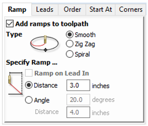
- Ramp: This is important! Set this to prevent the cutter from plunging vertically into the material. The cutter gradually cuts at an angle dropping into the material significantly reducing cutter wear, heat build-up and also the load on the router spindle and Z axis of the machine. If multiple passes are required due to the Pass Depth being less than the Cut Depth, the ramp moves are applied at the start of each level. All ramp moves are performed at the plunge rate selected for the current tool.
- Smooth
- This option creates a smooth ramp into the material using either the specified Distance or Angle
- When a Lead In distance has been specified, the option Ramp on Lead In disables the distance and angle options and automatically limits the ramp moves to only be on the lead in portion of the toolpath.
- Zig Zag
- This option ramps into the material by zig-zagging back and forth using either the specified Distance or Angle.
- The Distance option ramps into the material, zigging for the specified distance in one direction then zagging back over the same distance.
- The Angle option is typically used for cutters that cannot plunge vertically but have an entry angle specified by the manufacturer.
- Spiral
- Checking ✓ this creates a continual spiral ramp, these are only available when the toolpath does not include lead in moves.
- This option ramps into the material over the complete circumference of the profile pass. The angle is automatically calculated to ramp from the start point to full depth over the perimeter distance around the job.
- The rate at which the cutter ramps into the material is determined by the Pass Depth specified for the cutter. For example, Spiral Profiling set to 0.5 inch deep with a cutter that has a Pass depth of 0.5 inches or greater will spiral down in 1 pass. Editing the Pass depth to be 0.25 inch results in the 2 spiral passes around the profile.
- Smooth
- Order Not critical. Unless you have to reorder how the machine moves and cuts.
- Corners is special for v- bit (lettering bit) to make sharp corners on the outside of a shape. Typically, we don’t use this feature.
- Vector Selection: The software is set to “manual” at the beginning, which means you select each vector using a mouse, but this tool helps you select multiple vectors automatically based on conditions selected.