
This option opens the Pocket Toolpath form for machining 2D pockets. These toolpaths automatically compensate for the tool geometry – both diameter and angle.
(1) Cutting Depths
- Start Depth (D)
- Specifies the depth at which the pocket toolpath is calculated. When cutting directly into the surface of a job the Start Depth will usually be 0. If machining into the bottom of an existing pocket or stepped region, the depth of the pocket / step must be entered.
- Cut Depth (C)
- The depth of the toolpath relative to the Start Depth.
(2) Tool
- Clicking the Select button opens the Tool Database from which the required tool can be selected. See the section on the Tool Database for more information on this.
- Clicking the Edit button opens the Edit Tool form which allows the cutting parameters for the selected tool to be modified, without changing the master information in the database
- Pocket Toolpath.. used to create a deeper large area. This tool has some similar features with what we have mentioned before. So, let’s look at things that are different here.
(3) Use Larger Area Clearance Tool
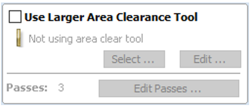
- Use Larger Area Clearance Tool
- If this option is selected two tools are used to clear the pocket. A large tool to do the bulk of the area clearance and a smaller tool (the first tool selected) to remove the remaining material and do a final profile pass.
- When a pocket toolpath is created, the Pass Depth value associated with the selected tool (part of the tool’s description in the Tool Database) is used to determine the number of passes needed to pocket down to the specified Cut Depth. However, by default Aspire will also modify the tool step down to reduce the total number of passes required to reach the desired cut depth. This can significantly reduce machining time of cutting pockets.
- The Edit Passes… button will open a new dialog that enables the specific number and height of passes to be set directly.
(4) Clear Pocket
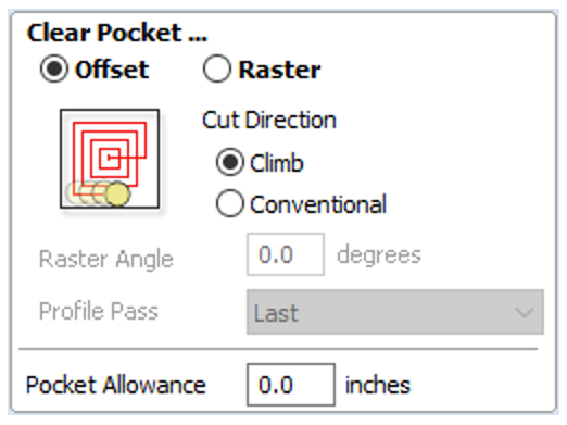
There are two choices of the type of fill pattern that will be used to clear away the area to be machined with the Pocket Toolpath, Offset and Raster.

Offset Calculates an offset area clearance fill pattern to machine inside the selected vector(s). Options for Cut Direction to be either: Climb (CCW) cutting direction Conventional (CW) cutting direction.

Raster Calculates a Raster based area clearance fill pattern to machine inside the selected vector(s). Cut Direction for the final pass to be either:
– Climb (CCW) cutting direction
– Conventional (CW) cutting direction

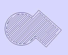
- Raster Angle
- Between 0 and 90°, where 0° is parallel to the X axis and 90° parallel to the Y axis.
- Profile Pass
- Used to clean up the inside edge after machining the pocket. This can be done either before the rastering (First) or after the rastering (Last). If ‘No Profile Pass’ is selected, you will need to calculate a profile pass manually to machine the pocket to size.
- Pocket Allowance
- This option is used to leave material on the inside of the pocket for the Profile Pass to clean-up. This is often very useful for ensuring the cutter does not mark the edge surface of the pocket when roughing out.
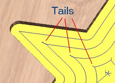
Note: When the stepover for a pocket fill is greater than 50% of the cutter/tip diameter the software automatically adds ‘Tail’ moves to the corner regions on the toolpaths to ensure material is not left on the job. You can see these in the diagram of a star being pocket machined below: