3D Cut Software
In this document, we will walk you through the basic interface of the program and how to prepare a 3D cut file for the ShopBot machine. This example shows how to mill a model that fits on one block of material. If your model is more complex and requires milling more than one piece, please consult the Fab Lab staff.
- After creating your 3D file, export it into .stl, or .obj. Open the file in the software by selecting “Load 3D File.” Left click to rotate the model; right click to zoom; left and right click to pan.
After a file is loaded, you will see these icons and options in the interface:
- Stage: the first two rectangle boxes at the top left tell you where you are in the 7-step process of making a file for the machine. You can click on icons or use the “Previous” and “Next” buttons.
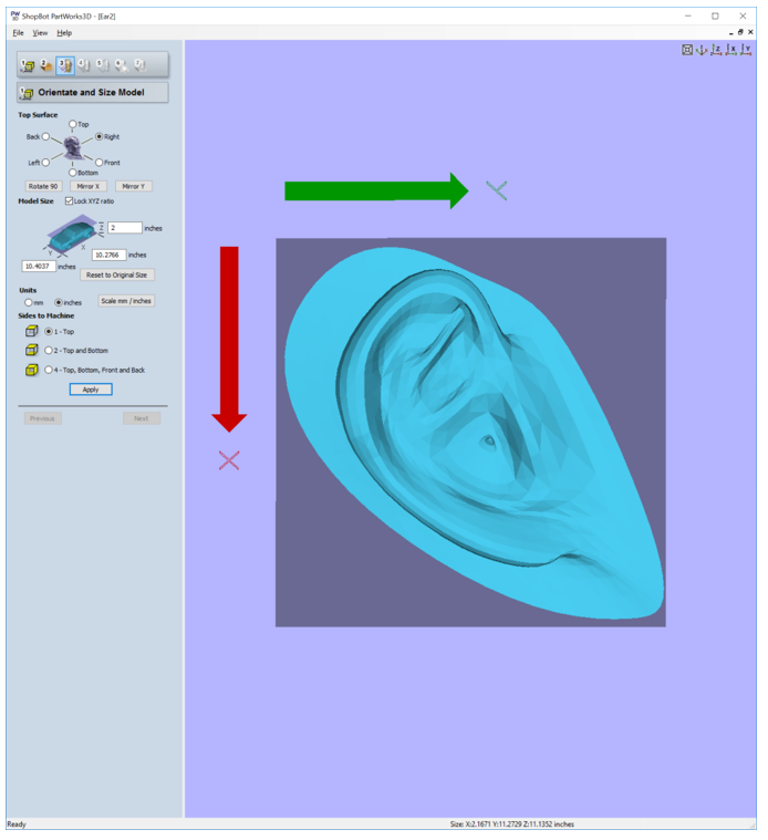
- Top Surface: To flip a model on surface of x and y
- Model Size: put the exact number of the model’s size. The numbers need to fit within the material you will use. If you will mill a model from one material (no sliced layers) you have to scale the z to fit with the material height. If the ratio doesn’t matter, uncheck the “Lock XYZ ratio” to change the number freely.
- Units: Stay in Inches because the machine works in inches.
- Sides to Machine: To choose how many sides you would like to carve
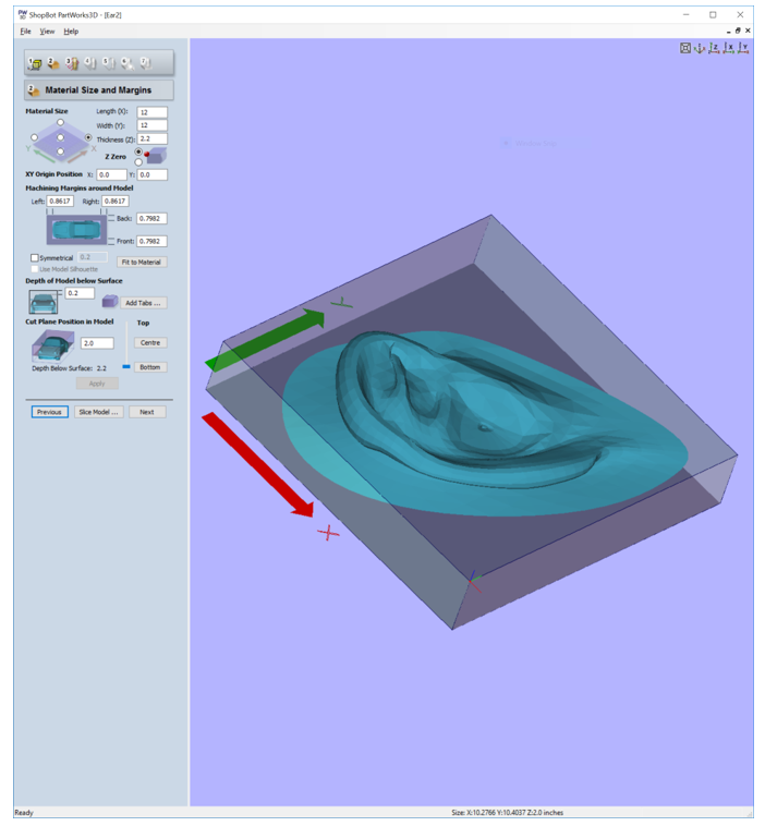
2. After choosing your settings in step 1, click Apply then Next, to move on to stage 2 — Material Size and Margins
- Set the XY Origin Position on the block by clicking on one of the 5 bullet options, and set the z zero to top or bottom. Usually, for milling a one-sided model the z is top.
- Put exact size numbers of the material. Remember that its height (thickness) should be at least slightly greater than the finished model height.
- XY Origin Position: leave 0.0 and 0.0
- Machining Margins around Model: To adjust the actual cutting area aka the area that machine is able to move in.
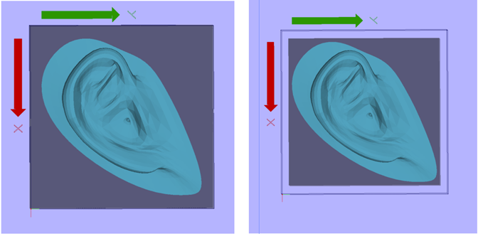
- Check Symmetrical and put wider than the bit you will use, e.g. bit diameter is 0.25 = you should put 0.26 in the box.
- Check Use Model Silhouette if you want the machine to cut following the model’s shape.
- Select “Fit to Material”, if you want the whole material to be the cutting area.
- Depth Below Surface: insert number calculated by the material’s thickness subtracted by the model’s height to adjust how deep the bit has to go in Z before start. For example, (material’s thickness) 2.2 – (model’s height) 2 = 0.2
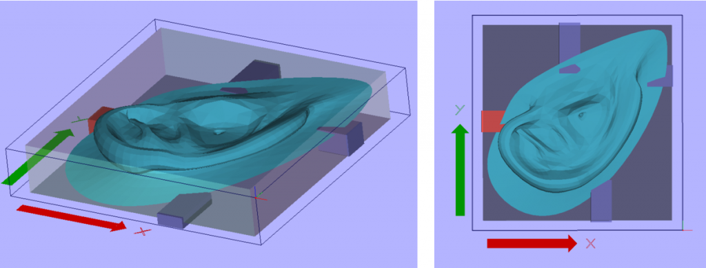
- Add Tabs: To add holders to the model and the leftover material. We need tabs to secure the finished pieces from moving while cutting. Below are some methods you should consider for adding tabs to your work.
- Width of tabs is originally parallel to the border of the cutting area. When selecting where to put the tab, the software will put the wider size close to the border. This can be changed by selecting another option in the drop down menu called “Side”. You should insert a width number that is not too small to hold your model stable, because you can always sand all these tabs out later.
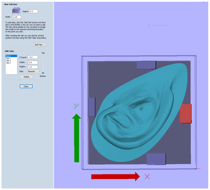
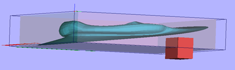
- Height is the thickness of tabs. Some models may not touch the ground of the material. Move the preview model around to see if your tabs touch the model.
- In the “Edit Tabs” section, you can edit values you have put into each tab. On the right, there is a slide of location for moving a selected tabs up or down.
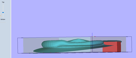
- Cut Plane Position in Model: To set how deep for a model to be cut. There are options for Top Centre and Bottom, if you do not want to actually mill out the whole model. But in most cases we do want to do that so go with Bottom.
- Slice Model: To separate layers of cutting. This function is useful for models that are higher than material the machine can cut. For more information, ask the staff.
3. Click “Apply” after you have done the in material size stage and move to stage 3 — Roughing Toolpath.
- Click “Select …” to select a bit. See the table of CNC bits for more information.
3.2 and 3.3 Cutting Parameters and Feeds and Speeds: This option will remain locked after selecting a bit, but you can select “Edit Parameters” to change it. Change the parameters according to the material, and please ask the staff if you’re unsure. Usually the harder the material is, the slower the speed.
- Pass Depth: To set how much deeper the bit will go from one pass to another.
** Pass depth should be narrower if running on a hard material.
- Stepover: To set how far (space) the bit will go from one point on the same level to another. (You will want to adjust this number in stage 4, Finishing Toolpath. Smaller numbers get smoother but slower; big numbers give small bulge lines on the surface but faster.)
- Toolpath Parameters is how the machine arm (spindle) will move.
- Rapid clearance gap is how high of the bit tip will go up above the surface when moving from one point to another. (You will see red lines appear on the screen after you hit calculate.) If the bit tip is going to collide with part of your material, make sure to increase the rapid clearance gap. Keep in mind that raising this number too high will affect the machining time.
- Machining Allowance is how the bit stays far on the edge of the model border. This should be matched with the selected bit diameter.
4. Do the same step in Finishing Toolpath but consider how you will select bits and other adjustments for your finishing cut. Hit Calculate and move to stage 5.
5. Stage 5 is unusual to be checked. We leave it blank. This stage is to cut out the model from the leftover material.
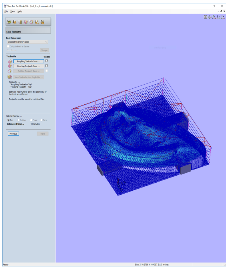
6. In stage 6, Preview Machining, you can preview how the outcome will be. The estimated time is usually not accurate but gives you some idea of how long it will take to finish everything.
7. Now, in the last stage, you must save the file into separate files of the toolpaths to run with the machine. ** Rename the file something unique and let yourself know which is the roughing and finishing path to avoid duplicated names with someone else’s files in the machine’s computer.