General steps required:
- Switching to the Manufacture workspace in fusion
- Creating a new manufacturing setup
- Creating and configuring a new toolpath for each cut (this guide covers 2D contour and 2D pocket operations )
- Exporting .gcode files for use in Bantam software
General considerations:
- It’s easier to generate toolpaths if you create your models in the Z up orientation
- You will need to create a new setup for each part that needs to be cut from a different piece of stock material
- It’s important to download and install the Bantam Tools Library for Fusion 360. Follow this link for the most updated version
- Currently the maximum pass depth that we use is 0.003 inches (or 0.0762 mm)
Generating toolpaths walkthrough
For this guide we’ll use the following 3D model, which is designed to be cut out of ¼” aluminum stock.

This part will require a 2D contour operation for the perimeter of the shape and a 2D pocket operation for the inside pocket.
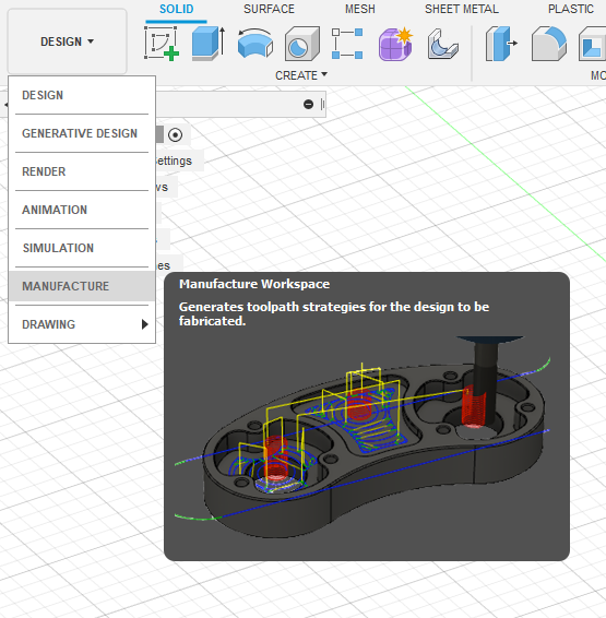
Switching to the manufacturing workspace
- Click the Change Workspace button on the top left corner of the window
- Select Manufacture
- You will see all the tool panels change to the manufacturing tools
Creating a new manufacturing setup
- Make sure you are in the Milling panel
- Under the Setup dropdown menu, click the New Setup button
- In the SETUP:SETUP1 panel that is now open, make sure you are in the Setup tab (the first one)
- Under Machine, select Autodesk Generic 3-axis with the Y axis on the table and XZ axis on the head
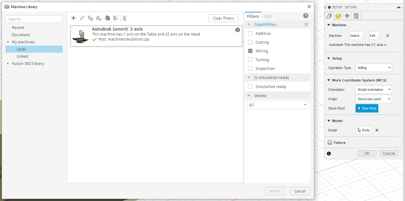
- If you have more than one body in your file, use the selection tool under Model to select the body you want to generate a toolpath for.
- Move to the Stock tab (second from the left)
- Under Stock, select Relative Size as the Mode
- Add some offset to Stock Side Offset (this is useful for visualizing contour cuts and tabs)
- Leave all other offsets at 0
- Click OK to finish creating the setup
Creating and configuring a new toolpath (2D contour)
- Make sure that the appropriate setup is active
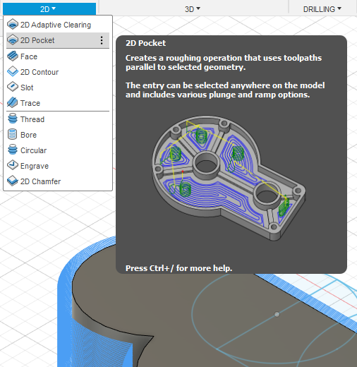
- In the Milling tab, click 2D, and select 2D Contour from the drop down menu
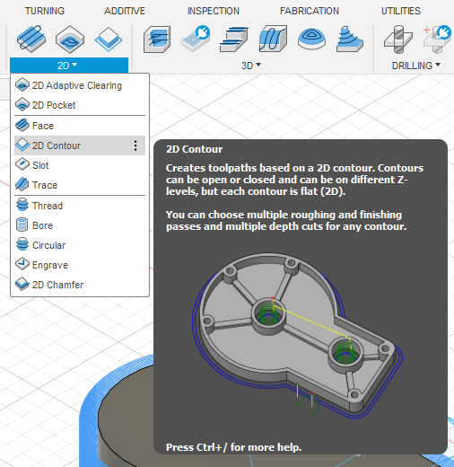
- In the 2D CONTOUR panel, in the Tool tab, select the appropriate tool from the Bantam Tools Fusion 360 Tool Library. For this example, we are using a 1/16” flat end bit.
- In the Geometry tab, under Contour Selection, select the bottom contour of the profile you need to cut
- Check the Tabs box
- Set the Tab Width and Tab Height (1.5 by .4 mm works for aluminum)
- Set the Tab Positioning to At Points
- Click the positions at which you want tabs along the selected contour

Bottom contour selected and tabs positioned
- In the Passes tab, check the Multiple Depths box
- Change the Maximum Roughing Stepdown and Finishing Stepdown to 0.0762 mm (3/1000”)

Pass depth configuration
- Hit OK
- In the Milling tab, click ACTIONS and select Simulate from the drop down menu
- Run the simulation and make sure everything looks OK (passes and tabs)
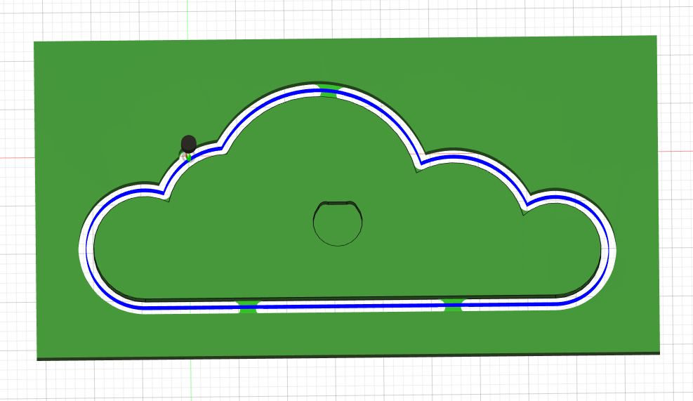
Contour simulations with passes (blue) and tabs
Creating and configuring a new toolpath (2D pocket)
- Make sure that the appropriate setup is active
- In the Milling tab, click 2D, and select 2D Pocket from the drop down menu
- In the 2D POCKET panel, in the Tool tab, select the appropriate tool from the Bantam Tools Fusion 360 Tool Library. For this example, we are using a 1/16” flat end bit.
- In the Geometry tab, under Pocket Selections, select the bottom bottom surface of the pocket you need to cut
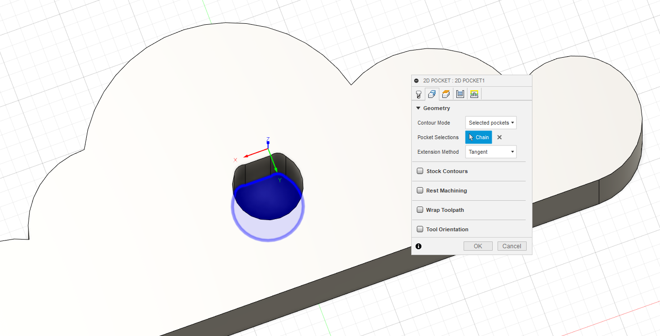
Pocket selection
- In the Passes tab, under Maximum Stepover, input half the diameter of the bit (or less). In this example, we are using a 1/16” bit, which is 1.5875 mm, so we are using a stepover of 0.75mm
- Check the Multiple Depths box
- Change the Maximum Roughing Stepdown and Finishing Stepdown to 0.0762 mm (3/1000”)
- Uncheck the Stock to leave box
- Hit OK
- In the Milling tab, click ACTIONS and select Simulate from the drop down menu
- Run the simulation and make sure everything looks OK (passes and perimeter of the pocket)
Exporting .gcode files for use in Bantam software
- Select one of the toolpaths in the Project Browser
- In the Milling tab, click ACTIONS and select Post Process from the drop down menu
- Under Post, click the drop down menu and select Choose from library
- Enter “Bantam” in the search box
- Click the Bantam Tools post and click Select
- Input a File name and select the Output folder
- Click Post
- You will find a .gcode file in the specified location
- Repeat this process for all your toolpaths
- The .gcode files will be ready to be loaded into the Bantam Software to perform the cuts
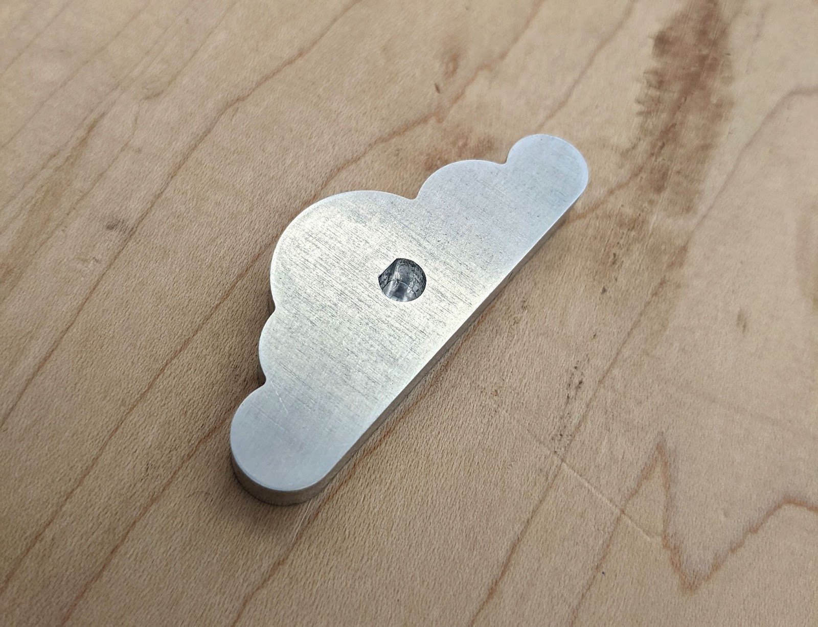
The finished piece