Machine specs
Working volume: 7” × 9” × 3.5”
Max traverse: 250 in/min
Spindle speed: 10,000-28,000 RPM
Tool Holding: ER-11 collet
Largest recommended shank size: 1/4”
Supported materials: Aluminum, Brass, Copper, ABS, Acrylic, Delrin, HDPE, Polycarbonate, Hardwoods, FR-1 (PCB Blanks), Machining Wax
More info: https://www.bantamtools.com/cnc-milling-machine
Bantam software notes (gcode workflow)
(based on software v. 2.3.7)
The bantam software is organized in tabs (on the left side of the UI). The tabs we need to navigate through to make a cut are:
- Initial Setup
- Material setup
- Plan setup
- Summary / run job
General steps required to start a cut:
- Preparing aluminum stock
- Homing the CNC
- Placing and fastening the aluminum stock to the CNC bed
- Loading a tool in the machine
- Opening a .gcode file
- Inputting the dimensions of the stock material you will be cutting (including any offsets)
- Probing the position of the material relative to the CNC bed
- Positioning the cut relative to the bed
- Checking all the settings and running the cut
General considerations for making cuts:
- Start with slow feed rates and very shallow pass depths
- Use the biggest bit that will fit the slots and holes of your cut
- Make sure your stock is securely fastened to the bed: this can be done with the toe clamps and L clamp, the vise or double sided tape (if your stock is large enough)
- Make sure there is some free space in the bed to do a Z probe (see fab lab staff if you are trying to make a cut that is as large as the CNC bed)
- Use a bit fan if there is one available for the particular bit you are using
- Pause the CNC every 30 minutes and vacuum any chips that have accumulated
- Make sure to only pause the CNC when the bit is not engaged in the material
- Clean the bit with isopropyl alcohol and a hook type tool (there may be adhesive or aluminum chips logged in the bit)
- Add a small drop of cutting oil to the bit before starting (but after doing a Z probe). We use Tap Magic XTRA-THICK
- Be ready to hit the emergency stop on the CNC
- The machine will not start the spindle nor allow you to run a cut if the machine door is open, in which case you will see the following warning

Milling a part – detailed walkthrough
Preparing aluminum stock
We can use the Bantam CNC to cut aluminum stock. So far we’ve tested 1/16” , ⅛” and ¼” stock thickness.
- To cut the aluminum stock to size, use the jigsaw with a metal blade.
- Use cutting oil on the blade and make sure to cut slowly, otherwise the aluminum will jam in the blade.
- If possible, leave a margin of around ½” in your stock
- It’s important to clean the edges of the aluminum stock with sandpaper, a file or a deburring tool in order for the material to sit flat against the bed.
- It’s also a good idea to wipe the stock with alcohol before cutting.
Homing the CNC
- Turn on the CNC machine, ensure the USB cable is connected and open the Bantam Tools software
- The software should prompt you to home the CNC, if it doesn’t, you’ll see the following warning in the center of the window

- To home the CNC, go to Jog in the bottom left corner of the window. This will open the jog control window. Hit the Home button and wait for the CNC to locate it’s home positions (it will take a minute) NOTE: if the machine is not homed, you will not be able to mill files, jog the bed, probe materials or install tools

Placing and fastening the aluminum stock to the CNC bed
- Go to Jog in the bottom left corner of the window. This will open the jog control window. Hit the Loading button and wait for the machine to bring the bed close to the CNC door.
- Clean the CNC bed and your aluminum stock with isopropyl alcohol. Make sure there are no aluminum chips or tape residue stuck to the bed.
- When making a cut that goes through the entire thickness of the stock, it’s important to use double sided tape on the back of the stock. This will create a small offset that will allow the bit to cut through the material without damaging the bed. It will also provide a better fixture.
- Lay your stock flat against the bed.
- If using tape, apply pressure to the stock
- Whenever possible, use the L-clamp and toe clamps to secure your stock

¼” aluminum stock with double sided tape ready to be placed in the bed

¼” aluminum stock loaded in the machine, secured with tape and clamps
Loading a tool in the machine
- In the Bantam software, go to the Initial Setup tab, click the Install Tool button (this can also be accessed through the Jog panel). The spindle will move to the center of the Bantam Tools Desktop CNC Milling Machine.
- Loosen the collet nut about halfway using the collet wrenches or your hands.
- Make sure the correct collet size is installed (we use ¼” and ⅛” sizes). If not, replace the collet for the one that matches the shank diameter of the bit you will use.
- Slide the tool into the collet all the way until it stops. Then back off ever so slightly.
- Use the collet wrenches to tighten the tool until it’s snug, but be careful not to over tighten it.
- In the Bantam software, select the appropriate tool from the drop-down menu.
- Click Next, and the spindle will move to the default tool touch-off location at the front right corner of the bed. Confirm that nothing is blocking the tool from touching the bed, and then click Start. If necessary, use the Jog controls to move the tool above an empty space in the bed.
- The machine will perform a touch-off on the CNC bed
- If you are using a ⅛” bit, you might want to use a bit fan, ask the fab lab staff about this
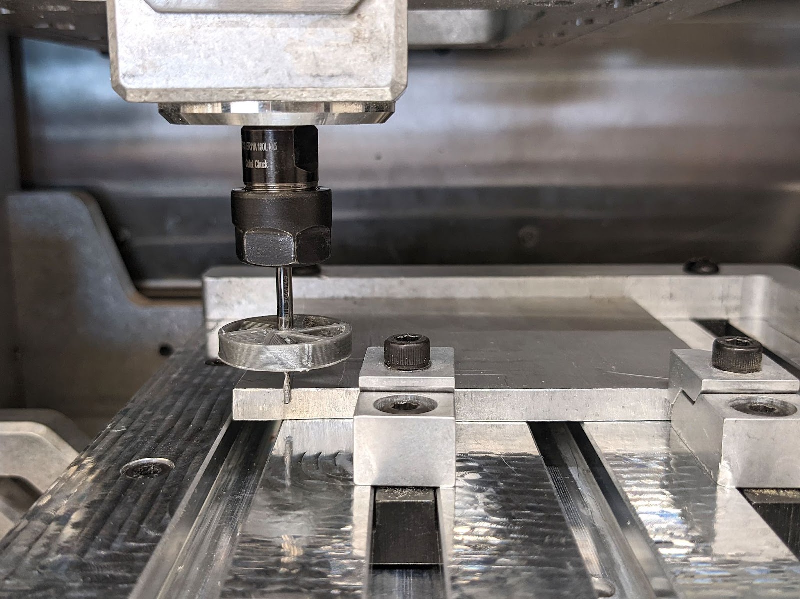
The tool install dialog with the jog panel, ready to start tool touch-off

1/16” bit with a ⅛” shank and a bit fan installed in the CNC
Opening a .gcode file
.gcode files contain the instructions for the CNC machine to perform a cutting operation
- Open the Initial Setup tab and click the blue Open File button
- Locate your .gcode file and open it
- The software will open a small pane for each file you open, use the dropdown menu to select the milling tool for each job
- You will also be able to see a visualization of your .gcode files in the 3D viewport
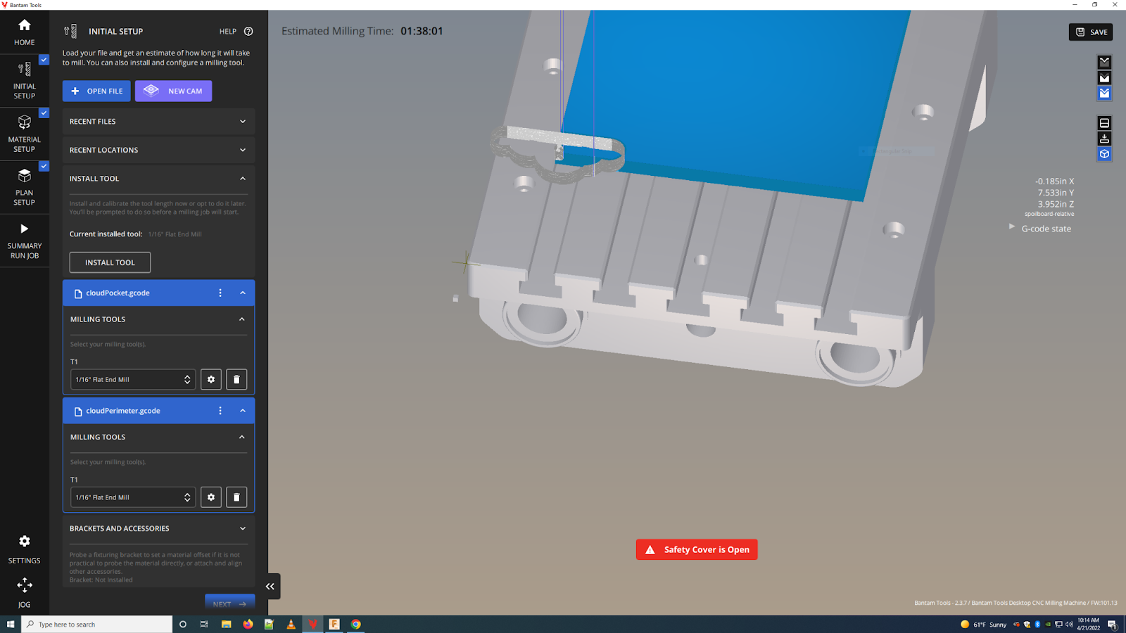
Initial setup tab with two .gcode files loaded and tools selected
Inputting the dimensions of the stock material
This step will let the Bantam software know the physical dimensions of the material you are working with
- Open the Material Setup tab
- Under Material Size use the X, Y and Z dialogs to input the width, height and thickness of your stock material. NOTE: you can change the unit system from imperial to metric at any time by going to Settings > Program Settings > Display Units
- Under Material Placement you can input a Material Offset Z offset (useful if your material is not directly touching the mill bed).
- If you are using tape to hold your stock in place, add the thickness of the tape as the Z offset
Probing the position of the material
This step will let the Bantam software understand where the stock material is positioned relative to the CNC bed
- Open the Material Setup tab
- Under Material Placement click on the green Material Offset Probing Routines. This will open the Probe Material panel
- Select Automatic Stock Probing

The automatic stock probing dialog
- The software will open the Jog dialog and prompt you to jog the bit to the front left corner of the stock material
- Make sure that the bit won’t collide with any clamps or fixtures and hit Start
- The bit will then attempt to make contact with the stock at three different points.
Probing the stock’s front edge
- If the probing is successful you will see a dialog with coordinates for your stock. Hit Accept

- NOTE: in order for the stock probing to work, there must be a direct electrical connection between the stock and the bed. This means that the probing will only work with conductive materials such as aluminum. If you are using tape to fix the aluminum in place, you need to create an electrical connection with a clamp or another metal object that touches both the stock and the bed.
Positioning the cut relative to the bed
This step will allow you to position your cut within the boundaries of your stock
- Open the Plan Setup tab, you will see a panel for each of your .gcode files
- Under Plan Offset, change the X and Y offset until you can see the cut correctly positioned within your stock (you can visualize this in the 3D viewport)
- Make sure all your files have the same offset values (we typically leave the Z offset at 0)
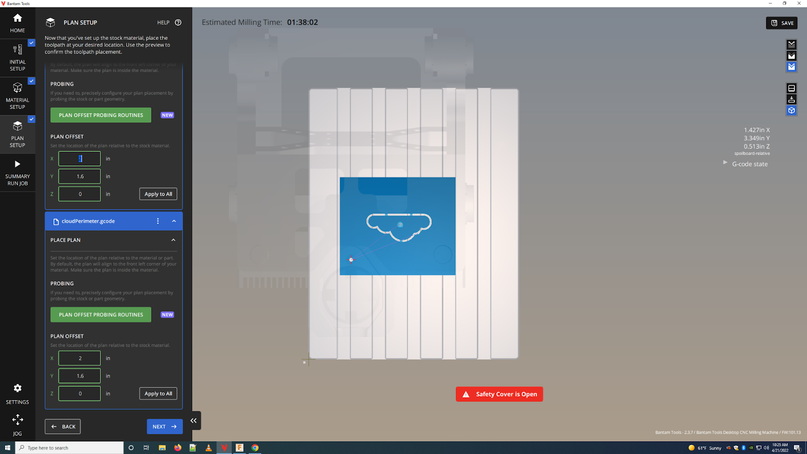
Two cuts with the same offsets, roughly centered in the stock
Checking all the settings and running the cut
- Open the Summary / Run Job tab
- Check that the preview in the 3D viewport looks OK
- Check that all the files you are cutting have the correct tool associated
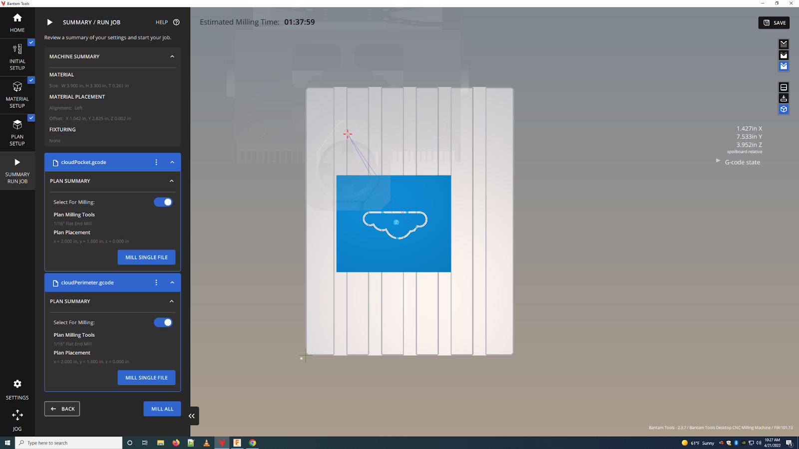
Everything looks good, ready to mill
- Add a drop of cutting oil (Tap Magic XTRA-THICK) to the bit
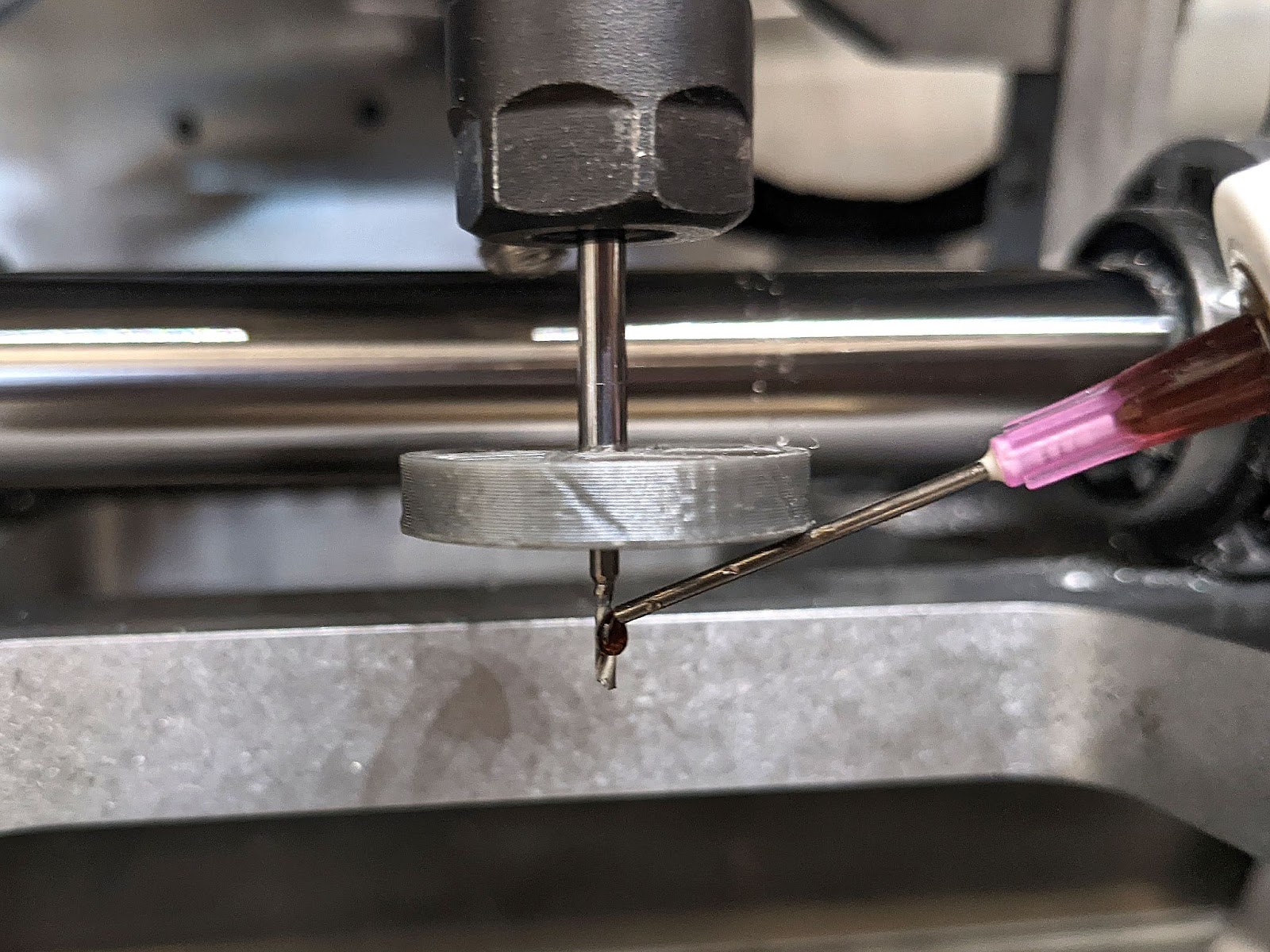
Adding oil to the bit before cutting
- Make sure the safety cover is closed on the CNC
- Hit Mill Single File inside the panel of the cut you want to make
- The machine will start milling the file

Starting a cut operation
- Always keep an eye on the machine as it is cutting
- If you are not using a bit fan, pause the machine every 30 minutes and vacuum the chips

Milling panel while performing a cut
- The Bantam software will show the Milling panel while cutting. You can Pause or Stop the cut from there.
- After you are finished cutting, remove the aluminum piece and remaining stock from the CNC
- The software will prompt you to run a clean-up routine. Hit Ok and follow the on-screen instructions to vacuum the interior of the machine.
- You are done! You can now remove tabs, sand and clean up your finished piece.

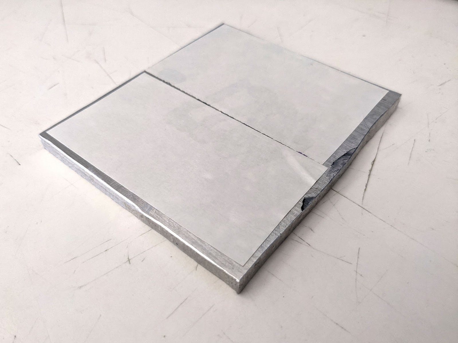
Aluminum stock after finishing the two cuts, still held in place by tabs
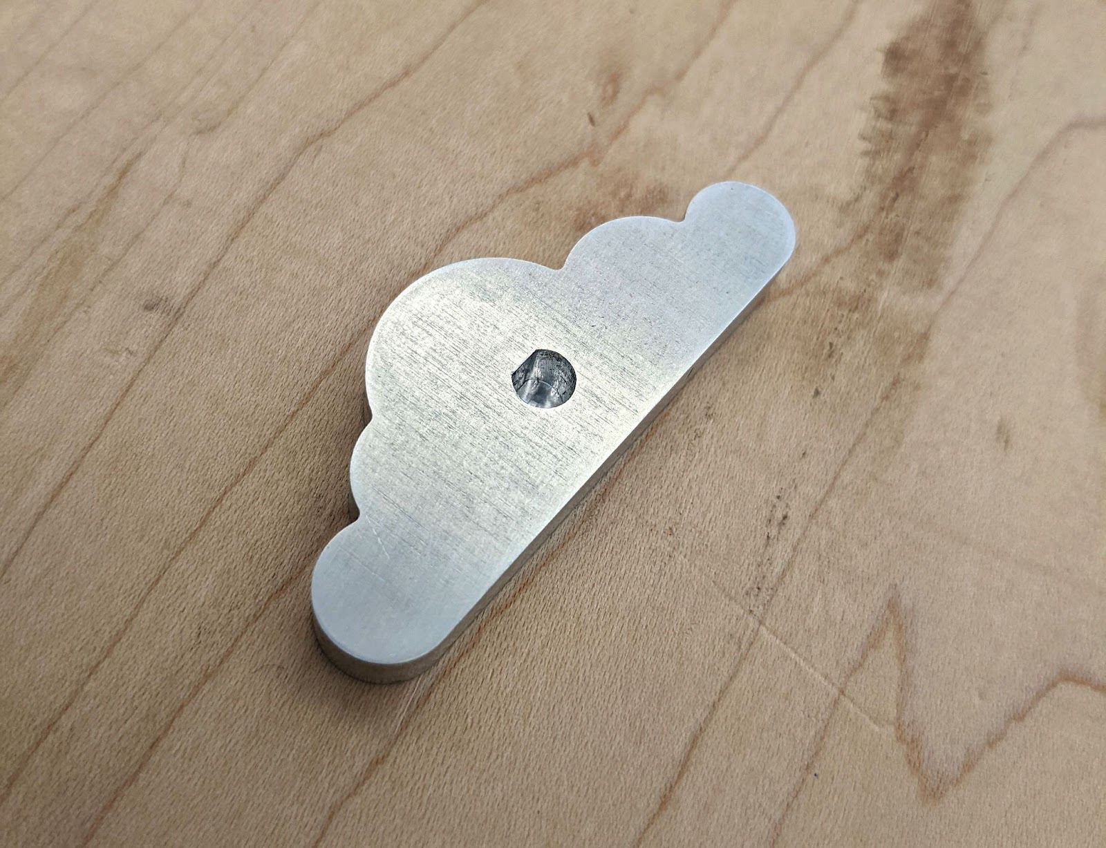
The finished piece, after removing tabs, sanding and cleaning
Using the Low-profile vise
Starting fall 2022, we are using the Bantam Fixturing Pallet with the Low-profile Vise in our desktop CNC machine. The vise allows secure and replicable fixturing of parts, as well as through cuts without need of double sided tape.
This diagram shows the nomenclature for the different clamping surfaces of the vise.

Probing the position of the vise
For most cuts, you won’t need to move the position of the fixed clamp. If you need to, follow this guide for instructions on installing and moving the fixed clamp. Once you move the clamp, you will need to probe its position inside the Bantam software.
- To probe the fixed clamp, make sure to remove the adjustable clamp from the bed as well as any stock material.
- Open the Initial Setup tab
- Open the Brackets and accessories drop down menu
- Under Low profile vise, click Remove if the vise was previously installed
- Click Locate, and follow the software prompts to probe the vise
- Click Accept once the machine has probed the vise. The Bantam software will store the position of the fixed clamp until you need to change its position again.
- You should be able to see the vise in the software’s 3D viewport

Ready to probe the fixed clamp of the low profile vise
Loading stock with the low-profile vise
- When loading stock material into the vise, you may use the Inner step, Outer step, or Bed to clamp your material
- Align your material against the fixed clamp, then align the adjustable clamp against the other side of the material
- Place the hex screws in the screw slots and tighten the adjustable clamp to the bed. Be careful not to over tighten the screws
- Tighten the adjustable clamp through its center hex screw
- Make sure the material is secure inside the clamp
- In the bantam software, open the Initial Setup tab
- Open the Brackets and accessories drop down menu
- Under Low profile vise, select the Surface option that matches the way your material is clamped: Inner step, Outer step, or Bed. When changing the Surface option, the software may prompt you to run through the install tool procedure.
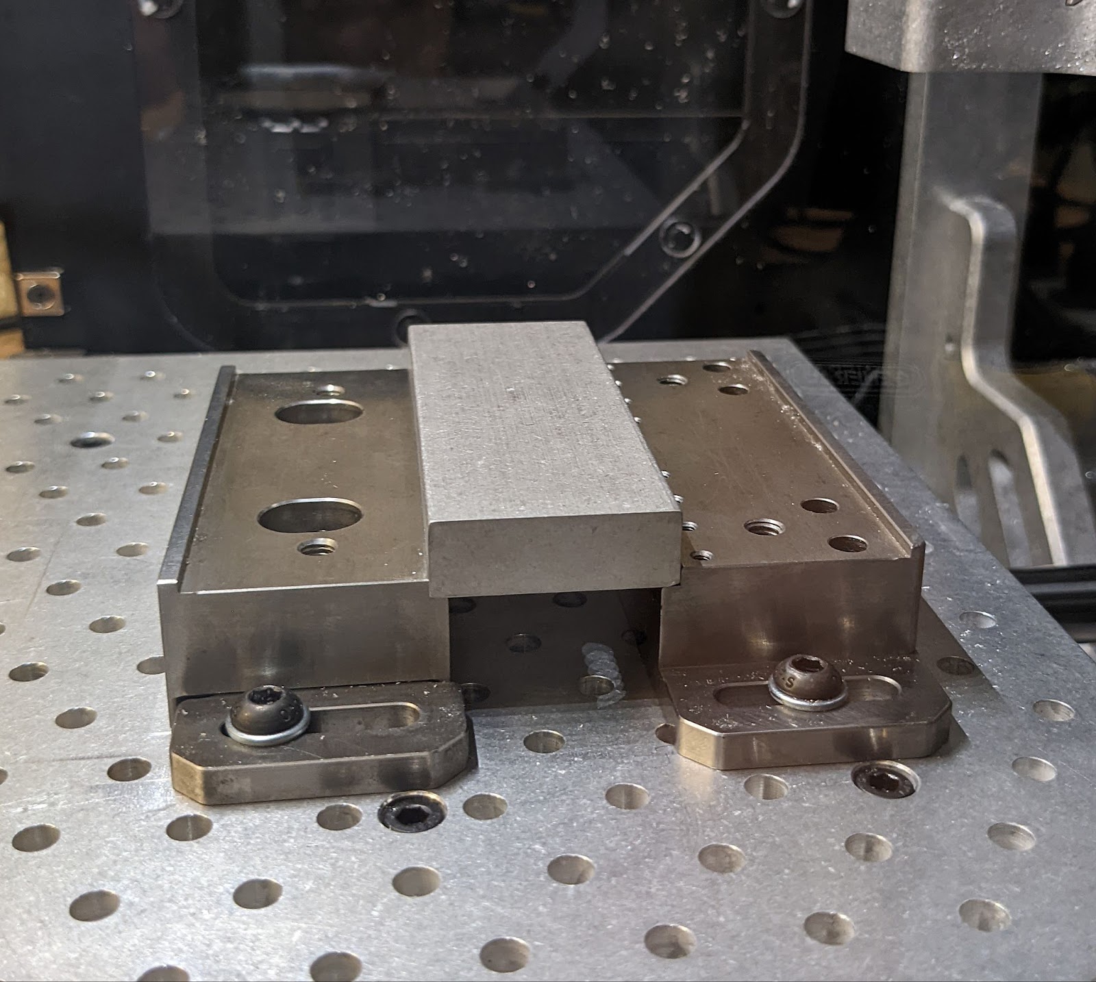
Aluminum stock set on the inner step of the low profile vise

The corresponding visualization in the Bantam software 3D viewport
IMPORTANT: loading an existing setup
When loading a previously saved cutting setup into the Bantam software, the Surface option isn’t loaded from the file and defaults to Bed (as of software version 2.4.13). You will need to reconfigure the appropriate surface in order to perform your cutting operations:
- Open the Initial Setup tab
- Open the Brackets and accessories drop down menu
- Under Low profile vise, select the Surface option that matches the way your material is clamped: Inner step, Outer step, or Bed. When changing the Surface option, the software may prompt you to run through the install tool procedure.
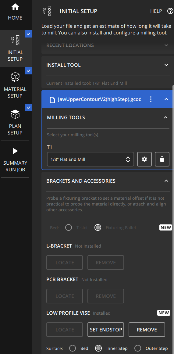
Low-profile vise options in the Bantam UI