Vcarve Pro 3D Milling

3D Cut Software

In this document, we will walk you through the basic interface of the program and how to prepare a 3D cut file for the ShopBot machine. This example shows how to mill a model that fits on one block of material. If your model is more complex and requires milling more than one piece, please consult the Fab Lab staff.

  1. After creating your 3D file, export it into .stl, or .obj. Open the file in the software by opening the “model” drop down menu and  selecting “Import Component/3D Model.” Left click to rotate the model; right click to zoom; left and right click to pan.

After a file is loaded, you will see these icons and options in the interface:

  • Initial Orientation: To flip a model on the surface of x and y.
  • Interactive Rotation: To freely rotate your 3D model.
  • Model Size: put the exact number of the model’s size. The numbers need to fit within the material you will use. If you will mill a model from one material (no sliced layers) you have to scale the z to fit with the material height. If the ratio doesn’t matter, uncheck the “Lock XYZ ratio” to change the number freely.
  • Units: Stay in Inches because the machine works in inches.
  • Zero Plan Position in Model: To position the depth of your 3D model inside your stock material.

2. After choosing your settings in step 1, click the OK button to move onto the “3D Model Tools” menu. In the modeling workspace you can:

  • Import a component or 3D model.
  • Look at and change the properties of your component.
  • Create a vector boundary for machining your component.  
  • Apply a smoothing filter to your component.
  • Scale the Z height of your model.
  • Slice your model into individual components.
  • Add a plane component to your model 

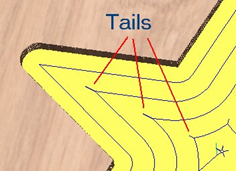
3. If you are cutting your shape out of the stock material you will need to add tabs to hold the model to the leftover material. To do this go to the “cliptart” tab at the bottom of the modeling menu on the left and then click on the “3D Tabs” folder. Find your desired tab shape and then drag and drop as many tabs as you need onto your model. From here you can adjust the dimensions of your tab by clicking the component properties icon back in the modeling menu. 4. After you are satisfied with the orientation, scale, and tabs of your model select the “Toolpaths” menu on the right side of the screen. You can “pin” it so it won’t close automatically when you click somewhere else. You should see these icons on the right side of the screen in your interface.

4. After you are satisfied with the orientation, scale, and tabs of your model select the “Toolpaths” menu on the right side of the screen. You can “pin” it so it won’t close automatically when you click somewhere else. You should see these icons on the right side of the screen in your interface.

4. Before we begin creating our toolpath we need to check our material setup. To do this click the button that says “Set…” under the Material Setup heading.

After you click the “Set..” button, you will see these icons and options in the interface:

  • Thickness: Adjust the thickness of your stock material.
  • XY Datum: Set the X,Y Zero position in relation to your stock material.
  • Z-Zero: Sets the Z Zero position to either the top of your stock material or to the machine bed.
  • Model Position in Material: This is where your model is in relation to your stock material. The light brown portion is the actual model and the dark brown is the amount of stock material above and below your model.  
  • Rapid Z gaps above Material: This sets the amount of distance between the tool and your material. You should not need to adjust this. 
  • Home / Start Position: You can adjust where you want the machine to start from, you will almost always keep this at X=0 , Y=0.

5. Once you have your material set up correctly select “3D Roughing Toolpath” to get started with a toolpath that will remove the bulk of your material with an end mill. After you click the roughing toolpath button, you will see these icons and options in the interface:

Toolpath Preview Tools

  • Preview Toolpath
    • This option animates the selected toolpath cutting into the material

  • Preview Control Simulation
    • The preview controls provide full video-like playback control of your toolpath. You can use this mode to analyze the tool movement in detail, step-by-step. To begin using Preview Control, click on either the Run, Single Step or Run to Retract buttons.

The Preview Control buttons are summarized below:

Run Begins Preview Control Simulation

Pause Temporarily halts the tool in its current position and enables the Stop button so you can exit Preview Control mode

Single Step Moves the toolpath on by one tool move

Run to Retract Runs the toolpath to the next retract move, then pauses the tool

Stop Exits Preview Control mode

Note: To cancel the process of previewing a toolpath using Preview Control, first click the Pause and then the Stop buttons.

  • Preview All Sides
    • This option animates all calculated toolpaths cutting into the material on both sides if working in a two sided environment without being in the ‘Multi Sided View’ mode (This option will be grayed out if working in a single sided setup)

  • Preview All Toolpaths
    • This option animates all calculated toolpaths cutting into the material

  • Preview Visible Toolpaths
    • This command allows you to identify a subset of toolpaths to be simulated, quickly and easily:
    • Isolate the toolpaths you wish to preview by un-ticking the visibility checkboxes of the other toolpaths in the Toolpath List.
    • Verify that the 3D View is only displaying the toolpath previews of the toolpaths you are interested in.
    • Click Preview Visible Toolpaths to begin the simulation.

  • Reset Preview
    • Resets the material back to a solid block

  • Save Preview Image
    • Saves an image of the 3D window as a BMP, PNG, JPG or GIF file

Tool

  • Clicking the Select button opens the Tool Database from which the required tool can be selected. See the section on the Tool Database for more information on this.
  • Clicking the Edit button opens the Edit Tool form which allows the cutting parameters for the selected tool to be modified, without changing the master information in the database
  • Pocket Toolpath.. used to create a deeper large area. This tool has some similar features with what we have mentioned before. So, let’s look at things that are different here.

Cutting Depths

  • Start Depth (D)
    • Specifies the depth at which the pocket toolpath is calculated. When cutting directly into the surface of a job the Start Depth will usually be 0. If machining into the bottom of an existing pocket or stepped region, the depth of the pocket / step must be entered.

  • Cut Depth (C)
    • The depth of the toolpath relative to the Start Depth.

Use Larger Area Clearance Tool

  • Use Larger Area Clearance Tool
    • If this option is selected two tools are used to clear the pocket. A large tool to do the bulk of the area clearance and a smaller tool (the first tool selected) to remove the remaining material and do a final profile pass.
    • When a pocket toolpath is created, the Pass Depth value associated with the selected tool (part of the tool’s description in the Tool Database) is used to determine the number of passes needed to pocket down to the specified Cut Depth. However, by default Aspire will also modify the tool step down to reduce the total number of passes required to reach the desired cut depth. This can significantly reduce machining time of cutting pockets.
    • The Edit Passes… button will open a new dialog that enables the specific number and height of passes to be set directly.

Clear Pocket

  • Clear Pocket

There are two choices of the type of fill pattern that will be used to clear away the area to be machined with the Pocket Toolpath, Offset and Raster.

Offset Calculates an offset area clearance fill pattern to machine inside the selected vector(s). Options for Cut Direction to be either: Climb (CCW) cutting direction Conventional (CW) cutting direction.

Raster Calculates a Raster based area clearance fill pattern to machine inside the selected vector(s). Cut Direction for the final pass to be either:
– Climb (CCW) cutting direction
– Conventional (CW) cutting direction

Clear Pocket – Offset Strategy
Clear Pocket – Raster Strategy
  • Raster Angle
    • Between 0 and 90°, where 0° is parallel to the X axis and 90° parallel to the Y axis.
  • Profile Pass
    • Used to clean up the inside edge after machining the pocket. This can be done either before the rastering (First) or after the rastering (Last). If ‘No Profile Pass’ is selected, you will need to calculate a profile pass manually to machine the pocket to size.
  • Pocket Allowance
    • This option is used to leave material on the inside of the pocket for the Profile Pass to clean-up. This is often very useful for ensuring the cutter does not mark the edge surface of the pocket when roughing out.

Note: When the stepover for a pocket fill is greater than 50% of the cutter/tip diameter the software automatically adds ‘Tail’ moves to the corner regions on the toolpaths to ensure material is not left on the job. You can see these in the diagram of a star being pocket machined below:

Offset larger than 50%
Tails to clean out corners